Seepage in Geotechnical Engineering
Water doesn’t just sit still in the ground. It moves constantly through soil pores. This movement, called seepage, is one of the most critical phenomena in geotechnical engineering.
Whether you’re designing a dam, building a foundation, constructing a tunnel, or managing groundwater, getting seepage wrong can turn your project into a disaster. But get it right, and you’ve got a structure that actually lasts.
What is Seepage?
Seepage is basically water sneaking through soil. When it rains, water doesn’t just sit on top of the ground? It soaks in and moves downward and sideways through the soil. That’s seepage. It’s invisible, it’s slow, and it’s always happening underground. Water moves through all those tiny pores between soil particles, always heading toward areas where there’s less pressure pushing on it.
Why Does Seepage Matter?
- Structural Stability When water seeps through or under a structure, it creates pore pressure that reduces soil strength. This weakens the foundation and can lead to settlement, tilting, or even collapse. A building that seems stable might fail years later due to slow seepage gradually weakening the soil beneath it.
- Uplift Forces Seepage beneath dams and foundations creates upward water pressure called uplift. This pressure literally tries to lift structures off the ground. Without accounting for uplift, a dam could float away or a foundation could heave upward, causing severe structural damage.
- Internal Erosion (Piping) When water seeps through soil at high velocities, it can carry soil particles away, creating internal voids and channels. This process, called piping, can start small but grow progressively until the entire structure fails suddenly. Many dam failures throughout history have been caused by uncontrolled piping.
- Slope Stability Seepage through slopes increases pore pressure, which reduces the friction holding soil in place. Slopes that are stable when dry can fail catastrophically after heavy rain when seepage increases dramatically.
- Settlement and Consolidation In clay soils, seepage controls how fast water drains from beneath a structure. Slow seepage means slow consolidation and prolonged settlement over months or years, while faster seepage in sandy soils means quicker settlement but shorter duration.
The Role of Permeability
Sandy Soils have large pores and high permeability. Water flows through them quickly, often within hours or days.
This is why sandy foundations typically settle quickly but don’t experience long-term consolidation problems.
Silty soils have medium permeability.
Water moves through them at moderate rates, creating intermediate seepage conditions.
Clay soils have very small pores and low permeability. Water moves through them extremely slowly, sometimes taking years or decades to fully drain.
This is why clay foundations can continue settling for years after construction.
Flow Nets
Engineers use a graphical representation called a flow net to visualize and calculate seepage. It is essentially a map showing how water moves underground and where the water pressure is equal.
A flow net consists of two set of lines:
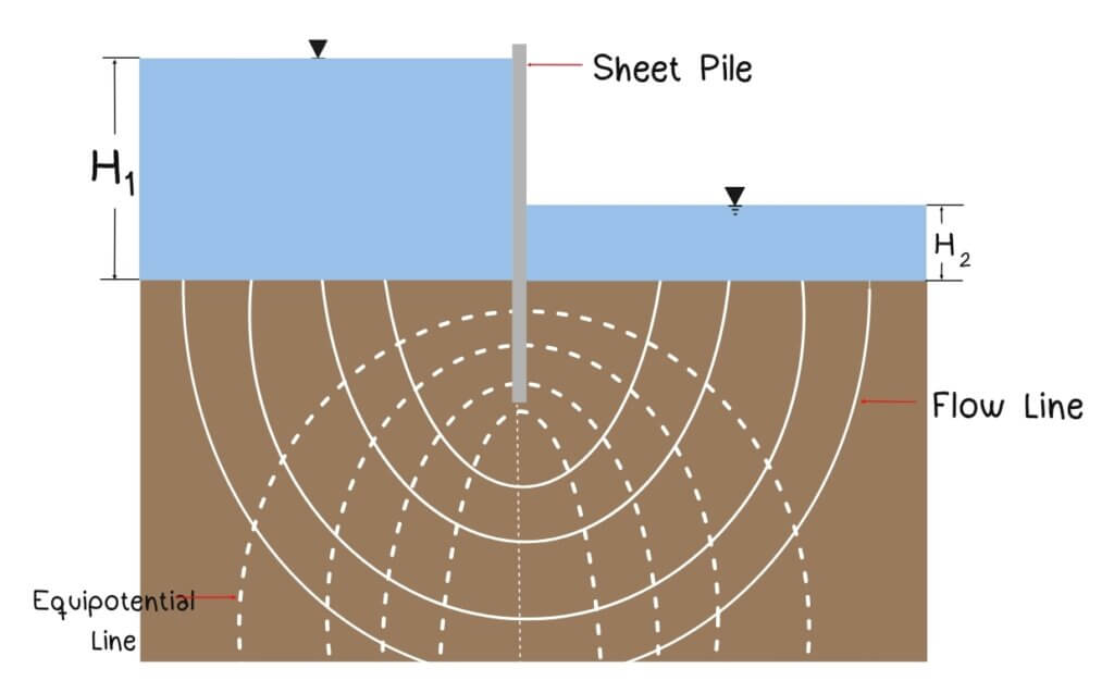
- Equipotential Lines: They run perpendicular to the direction of the water flow. These are lines connecting points where the total head (potential energy) is the same. Along any potential line, the water pressure and elevation combine to give the same value everywhere on that line.
- Flow Lines: Show the path that water particles follows as they seep through soil. Think of them as the routes water takes undergroud. They always cross equipotential lines at right angles.
Flow nets are based on fundamental principles of groundwater flow. For flow through an isotropic medium (soil where permeability is the same in all directions), the continuity equation requires that these two families of curves exist and that the intersect at right angles.
Why right angles? Because water flows in the direction of the steepest pressure gradient, which is perpendicular to equipotential lines.
The foundation of this is the Darcy’s Law, which descrives how water flows through porous media:
![]()
where:
Q = flow rate
k = coefficient of permeability
i = hydraulic gradient
A = cross-sectional area of which water flows
By drawing a flow net carefully, engineers can determine:
- Seepage Loss
- The total seepage quantity
- Uplift Pressure
- Pore pressure at any point in the soil
Characteristics of Flow Nets
- Orthogonality: Flow lines and equipotential lines must intersect at right angles (90 degrees). This isn’t just aesthetic; it’s a mathematical requirement. If your lines don’t cross at right angles, your flow net is wrong and your calculations will be off.
- Approximate Squares The shapes formed between adjacent flow lines and adjacent equipotential lines should be approximate squares (or curvilinear squares if the flow path curves). This means the width and length of each element should be roughly equal.
- Smooth Curves Flow lines and equipotential lines should be smooth curves without sharp angles or abrupt changes in direction. Sudden changes indicate errors in construction.
How to Calculate seepage from a Flow Net
Step 1: Define Flow Channels: A flow channel is the strip between two adjacent flow lines. Count how many flow channels exist in your flow net. Call this number Nf.
Step 2: Count Equipotential Drops: Count the number of equipotential intervals (the spaces between adjacent equipotential lines). Each interval represents an equal drop in head. Call this number Nd.
Step 3: Calculate Total Head Loss: Determine the total head difference between upstream and downstream. This is the driving force for seepage. Call this H.
Step 4: Apply the Flow Net Formula: The total seepage per unit length (perpendicular to the cross-section you’re analyzing) is:
![]()
Where:
q = seepage per unit length
k = coefficient of permeability
H = total head ![]() = number of flow
= number of flow ![]() = number of equipotential drops
= number of equipotential drops
Seepage through Isotropic Soil
![]()
Seepage through Anisotropic Soil
![]()
Pressure Head Drop
![]()
Real-World Consequences of Uncontrolled Seepage
Teton Dam Failure (1976) The Teton Dam in Idaho failed catastrophically within months of filling because piping occurred through the dam foundation. Uncontrolled seepage created a pipe that widened until the entire structure collapsed, releasing billions of gallons of water and causing massive destruction.
De the Funès Dam Failure (France, 1959) Piping through the dam foundation led to sudden failure and loss of life. The event highlighted how critical it is to control seepage pathways.
Slope Failures Heavy rainfall events that increase seepage through slopes cause numerous landslides worldwide every year. These failures often occur on slopes that had stood stable for decades because increased pore pressure from seepage reduced the safety margin below the failure threshold.
Conclusion
Seepage is more than just water moving through soil—it’s a fundamental force that engineers must understand, calculate, and control. Whether you’re designing a small retaining wall or a massive dam, whether you’re building on clay or sand, seepage analysis is essential to ensuring safety and performance.
By understanding permeability, hydraulic gradients, and seepage pathways, engineers can design structures that withstand water pressure, resist piping, minimize settlement, and protect the environment. The next time you see a dam, a basement wall, or any structure built near water, remember that behind its safe performance is careful seepage analysis and thoughtful design.
📍This post is part of GEOTECHNICAL COMPLETE Lessons. Also, if you want to avail the complete Cheat Sheet just click the “image” below.

References:
Das, B. M. (2013). Fundamentals of geotechnical engineering. Cengage Learning.

