Braced Cuts in Geotechnical Engineering
What you’ll learn
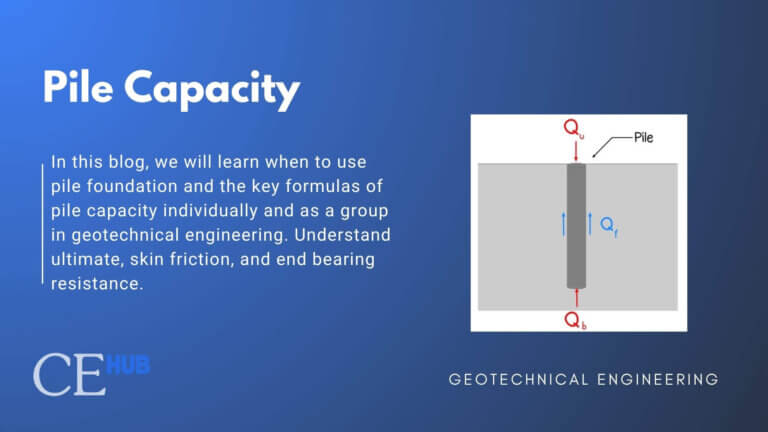
What is Braced Cuts in Geotechnical Engineering?
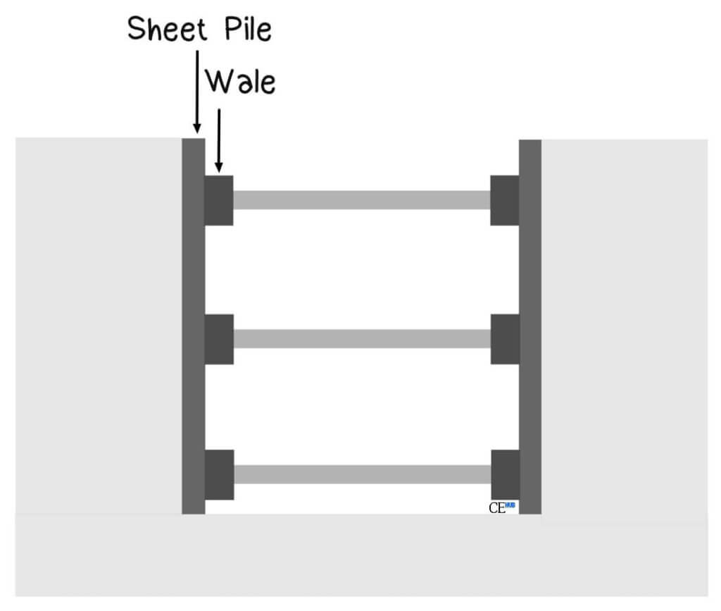
A braced cut is a temporary or permanent vertical excavation support system that consists of vertical or near-vertical walls (typically sheet piles, soldier piles, or concrete walls) held in place by horizontal structural members called struts or braces.
Types of Braced Cut Systems
1. Steel Sheet Pile Systems
Steel sheet piles are interlocking steel sections driven into the ground to form a continuous wall. They are particularly effective in cohesive soils and areas with high groundwater levels.
Pros:
- Water retention capabilities
- Suitable for various soil conditions
- Provides continuous support
Cons
- Limited depth capabilities in hard soils
- May cause vibrations during installations
- Intensive Labor
2. Soldier Pile and Lagging Systems
This system consists of steel H-piles or wide-flange beams (soldier piles) installed at regular intervals with horizontal timber or concrete lagging placed between them as excavation proceeds.
Pros
- Cost-effective for moderate depths
- Good visibility of soil during excavation
- Flexible installation sequence
Cons
- Limited water retention
- Need stable soil conditions
- Intensive labor
3. Diaphragm Walls
Reinforced concrete diaphragm walls are constructed in place before excavation begins. These permanent or semi-permanent structures provide excellent structural capacity and water retention.
Earth Pressure for Braced Cuts
Rankine Active Pressure for Reference
For a cohesionless backfill with friction angle  and unit weight
  :
:

![\[K_a=\frac{1-sin \varphi}{1+sin \varphi}\]](https://civilengghub.com/wp-content/ql-cache/quicklatex.com-11ef709886cb72853d138551255c5071_l3.png "Rendered by QuickLaTeX.com")
For Sands,
Peck (1969) provided the envelope of apparent-lateral pressure diagrams for design of cuts in sand. This enveloped is illustrated in figure 1
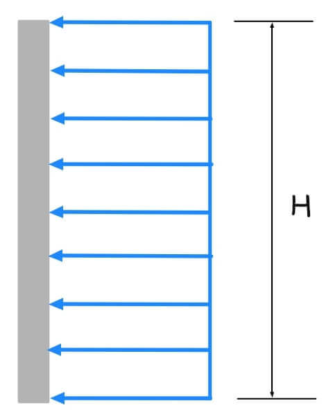
![\[\sigma_a=0.65K_a \gamma H\]](https://civilengghub.com/wp-content/ql-cache/quicklatex.com-1ee794a42a41e5776f4035a6915c8fb9_l3.png "Rendered by QuickLaTeX.com")
where:
= unit weight  = height of the cut
 = Rankine active pressure coefficient =
 = effective friction angle of sand
For Clays:
Peck (1969) also provided the envelopes of apparent-lateral pressure diagrams for design of cuts in soft to medium clay and stiff clay.
Soft to medium Clay
![\[\frac{\gamma H}{c}>4\]](https://civilengghub.com/wp-content/ql-cache/quicklatex.com-3043ad4fe5ba4135e505ec223e4bc23b_l3.png "Rendered by QuickLaTeX.com")
where:
c = undrained cohesion 
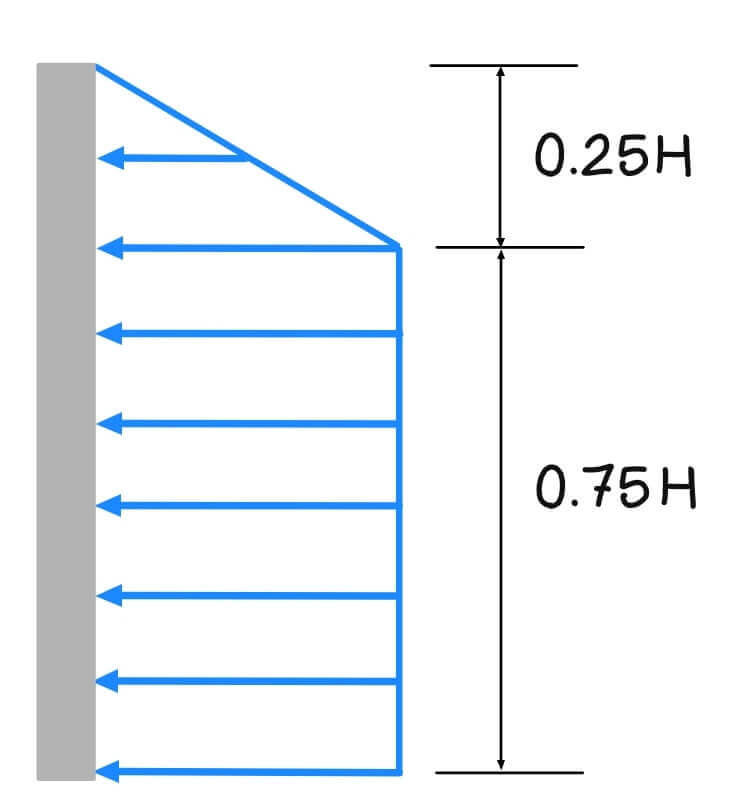
or (which is larger)

Stiff Clay
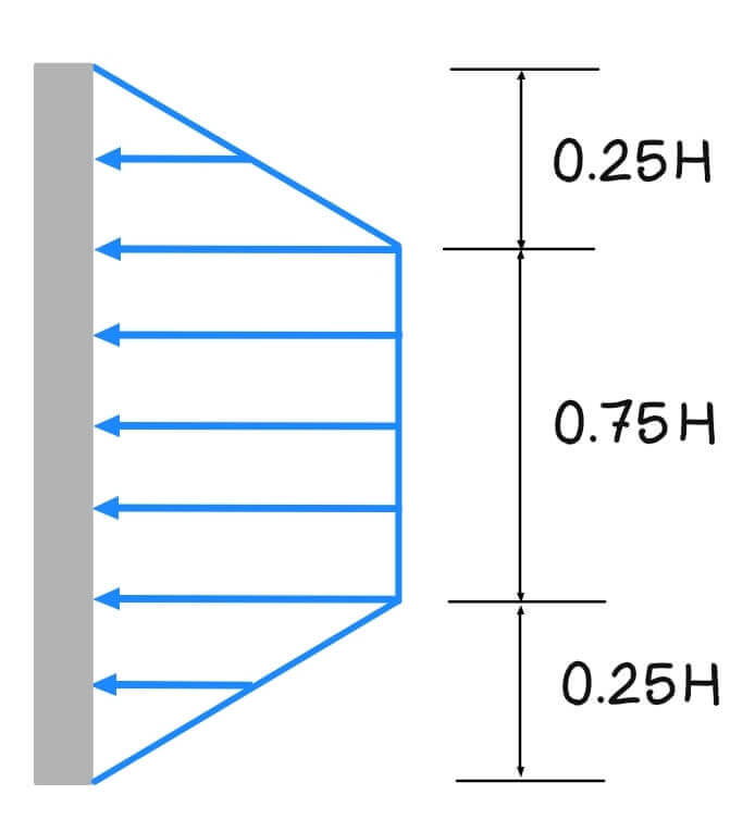
![\[\sigma_a=0.2\gamma H \: to \: 0.4\gamma H \]](https://civilengghub.com/wp-content/ql-cache/quicklatex.com-bce090e239d4806cc8db85c010e6fde3_l3.png "Rendered by QuickLaTeX.com")
Pressure Envelopes on Cuts in Layered Soils
Layers of Sand and Clay
where: = total height of the  = unit weight of the clay
 = unit weight of the sand
 = height of the sand
  = lateral earth pressure coefficient for the sand layer
  = effective angle of friction of
  = unconfined compression strength of
  = a coefficient of progressive failure
Layers of Clay
where: = undrained cohesion
 = thickness of the layer
References:
Holtz, R. D., & Kovacs, W. D. (1981). An introduction to geotechnical engineering. Prentice
Hall.Das, B. M. (2013). Fundamentals of geotechnical engineering. Cengage Learning