Fluid Flow Measurement
What is Fluid Flow Measurement?
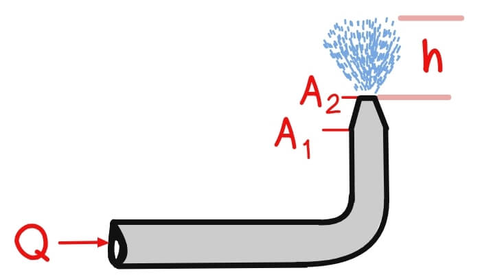
Fluid flow measurement means finding the volume (or mass) of fluid passing a given point over time. The most common form is volumetric flow rate: Q=A⋅vQ = A \cdot vQ=A⋅v
Where:
Q = Flow Rate (m³/s or L/s)
A = Cross-sectional area (m²)
v = Average Fluid Velocity (m/s)
Device Coefficients
Coefficient of Velocity, Cv
It is the ratio of the actual velocity and theoretical velocity.
![\[C_v=\frac{V_A}{V_T}\]](https://civilengghub.com/wp-content/ql-cache/quicklatex.com-e3f8515c66846502b4a79ba98fe5dcaa_l3.png "Rendered by QuickLaTeX.com")
where: 

The coefficient of velocity accounts for energy losses due to friction and turbulence as the fluid flows through an orifice or opening. These losses mean the actual velocity is always less than the theoretical velocity.
![\[V_t>V_a\]](https://civilengghub.com/wp-content/ql-cache/quicklatex.com-137b6797847d788095eac2cdd689d1d8_l3.png "Rendered by QuickLaTeX.com")
Understanding Cv helps engineers design system that compensate for velocity losses. In application like:
- Spray Nozzles
- Fire Hydrants
It is crucial to determine the actual exit velocity for accurate spray distance and coverage patterns.
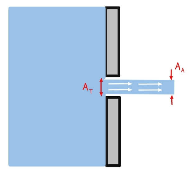
Coefficient of Contraction, Cc
It is the ratio of the area of the stream of jet to the area of the opening.
![\[C_c=\frac{A_A}{A_T}\]](https://civilengghub.com/wp-content/ql-cache/quicklatex.com-89b4d3e67bdc69f6224c716c26eae9d8_l3.png "Rendered by QuickLaTeX.com")
Coefficient of Discharge, Cd
The coefficient of discharge is perhaps the most practical of the three coefficients, representing the ratio of actual discharge (flow rate) to theoretical discharge through an orifice or opening.
![\[C_d=\frac{Q_a}{Q_t}\]](https://civilengghub.com/wp-content/ql-cache/quicklatex.com-6dee8236050afdbb6a3accc914e6095f_l3.png "Rendered by QuickLaTeX.com")


where:

🔍 Why We Use Flow Coefficients
In real systems, fluid doesn’t behave perfectly. There’s friction, turbulence, and shape-related losses. To account for these, we use empirical coefficients:
| Coefficient | Symbol | What It Represents |
|---|---|---|
| Discharge coefficient |  | Actual vs. theoretical flow rate |
| Velocity coefficient | | Actual vs. theoretical jet velocity |
| Contraction coefficient | | Jet area vs. orifice area (due to vena contracta) |
Flow Measurement Devices
Orifice
An orifice meter consists of a flat plate with a circular hole installed perpendicular to flow in a pipe. It’s the most common flow restriction device due to its simplicity and low cost.
Types of Orifice
- Sharp-edged (thin-plate) orifice
- Thick Orifice
- Rounded Orifice
Venturi Meters
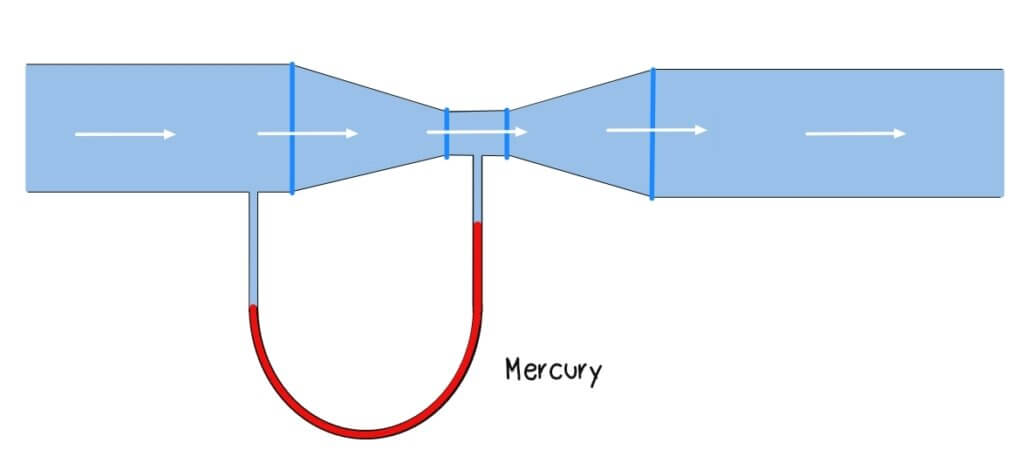
A venturi meter features a gradual contraction (convergent cone), throat section, and gradual expansion (divergent cone), designed to minimize energy losses.
Pitot Tube
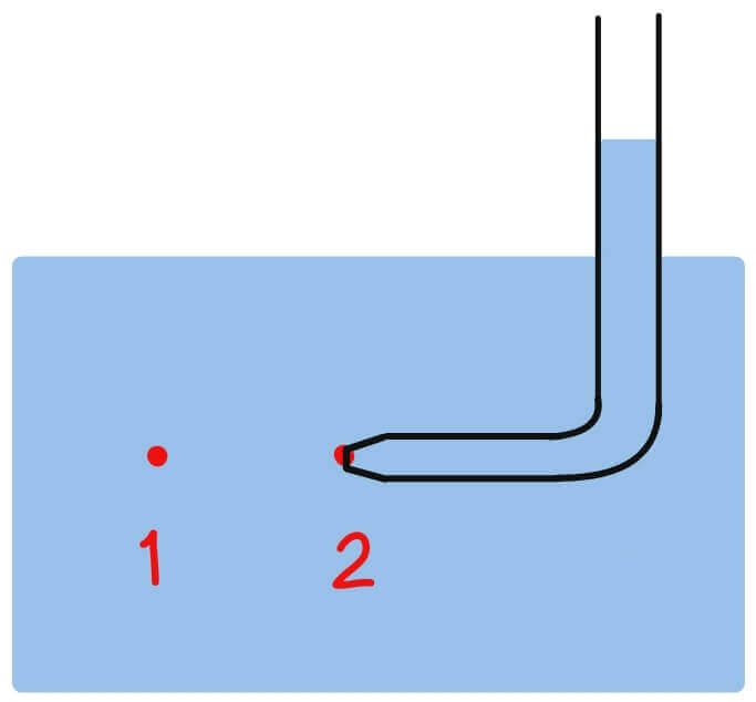
A pitot tube measures local velocity by comparing stagnation pressure to static pressure.
Types of Pitot Tube
- Simple Pitot Tube: Measure stagnation pressure only
- Pitot-static Tube: Stagnation and static pressure ports
- Averaging Pitot : Multiple sensing points accross pipe diameter
Flow Nozzles
A flow nozzle is a smooth, contoured restriction that combines features of orifices and venturi meters. It provides better accuracy than orifices with less pressure loss, at moderate cost.
References:
Engineering Toolbox. (2019). Orifice, Nozzle and Venturi Flow Rate Meters. Engineeringtoolbox.com. https://www.engineeringtoolbox.com/orifice-nozzle-venturi-d_590.html
Miller, R. W. (1983). Flow Measurement Engineering Handbook. McGraw-Hill Companies.
Want the Complete Fluid Flow Measurement Cheat Sheet?
Get the Ultimate Fluid Mechanics Cheat Sheet

Fluid Mechanics and Hydraulics Cheat Sheet
Master the fundamentals of fluid mechanics with this complete Fluid Mechanics Cheat Sheet designed for civil engineering students and exam reviewers. This digital guide summarizes the most important formulas, concepts, and equations. Not only it is aesthetic but also categorized by topics.