Series and Parallel Pipe Systems
In hydraulic engineering, pipe networks rarely consist of single, uniform pipes. Instead, real-world systems involve complex arrangements of pipes with varying diameters, lengths, and materials. Understanding how these pipes interact when connected is fundamental to designing efficient water supply systems, analyzing flow distribution, and predicting pressure losses throughout the network.
Bernoulli’s Equation (Energy Equation)

where:


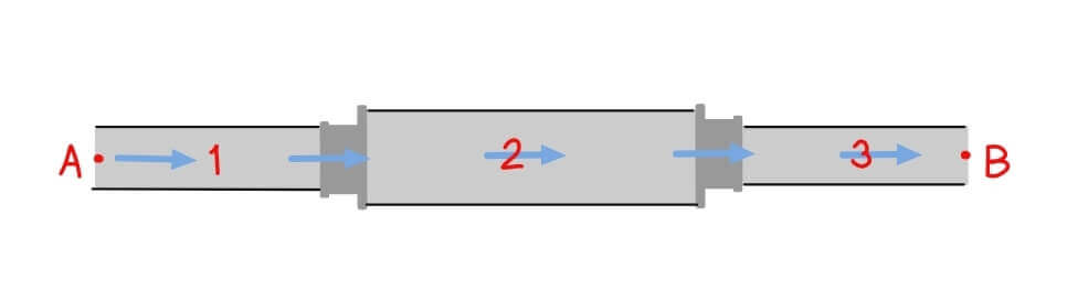
Series Pipe System
Series pipe systems consist of pipes connected end-to-end in a sequential arrangement. In this configuration, fluid flows through one pipe section before entering the next, creating a continuous flow path from inlet to outlet.
![\[Q = Q_1=Q_2=Q_3\]](https://civilengghub.com/wp-content/ql-cache/quicklatex.com-fc42f96227b2e5e52b8fddb78e602f5a_l3.png "Rendered by QuickLaTeX.com")
Head Loss
![\[h_{a,b} = h_1+h_2+h_3\]](https://civilengghub.com/wp-content/ql-cache/quicklatex.com-00d56bf4c0db91bc62469938f7db79c7_l3.png "Rendered by QuickLaTeX.com")
Key Characteristics
- Same volumetric flow rate (Q) passes through each pipe section
- Total Head Loss equals the sum of individual head losses in each pipe
- Different pipe diameters have different velocities each section
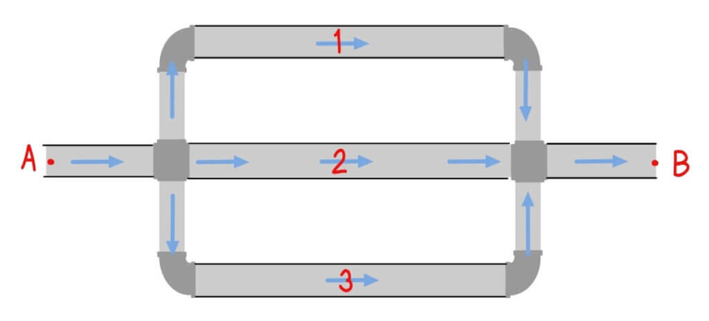
Parallel Pipe System
Head Loss
![\[h_{a,b} = h_1=h_2=h_3\]](https://civilengghub.com/wp-content/ql-cache/quicklatex.com-7c6753a7e5f152d3aea66f0eb12363a9_l3.png "Rendered by QuickLaTeX.com")
Key Characteristic
- Flow divides among the parallel branches
- Head loss is identical across all parallel paths
- Each branch can have different diameters, lengths and roughness coefficients
Fundamental Energy Principle
In analysis of series and parallel pipe systems, we based it using Bernoulli’s Equation (Energy Equation), which describes the conservation of energy in flowing fluids. Between any two points in a pipe system:

where:
P/γ = pressure head
V²/2g = velocity head
z = elevation head
hf = friction head loss
hm = minor head losses
Friction Loss Equations (Velocity Form)
Friction loss is the energy dissipated due to fluid friction with pipe walls. Several empirical formulas are commonly used to calculate friction losses in pipe systems.
Here are the examples of common derived friction loss.
Darcy-Weisbach Formula
The most fundamental and universally applicable friction loss equation:
![\[h_f=\frac{fL}{D} \frac{v^2}{2g}\]](https://civilengghub.com/wp-content/ql-cache/quicklatex.com-445384d5a9fae1796da3f9848a2e46c5_l3.png "Rendered by QuickLaTeX.com")
where:
hf = friction head loss (m)
f = Darcy friction factor (dimensionless)
L = pipe length (m)
D = pipe diameter (m)
V = flow velocity (m/s)
g = gravitational acceleration (9.81 m/s²)
Manning’s Equation
Commonly used for gravity flow in pipes and open channels:
![\[V= \frac{R^{2/3}S^{1/2}}{n}\]](https://civilengghub.com/wp-content/ql-cache/quicklatex.com-03700cc6abd102684a87e94da5590899_l3.png "Rendered by QuickLaTeX.com")
where:
V = average velocity (m/s)
R = hydraulic radius (m)
S = energy slope (m/m)
n = manning’s roughness coefficient
Friction Loss (Discharge Form)
Darcy-Weisbach Formula
![\[h_f=\frac{0.0826fLQ}{D^5}\]](https://civilengghub.com/wp-content/ql-cache/quicklatex.com-76e089b62b9e4b1a9c4874aeddb64178_l3.png "Rendered by QuickLaTeX.com")
Where:
Q = discharge (m³/s)
Manning’s Formula
![\[h_f=\frac{10.29n^2LQ^2}{D^{16/3}}\]](https://civilengghub.com/wp-content/ql-cache/quicklatex.com-6875488d3e8cba4e3aef8ff7fba2e96e_l3.png "Rendered by QuickLaTeX.com")
Where:
n = Manning’s roughness coefficient
Q = discharge (m³/s)
L = pipe length (m)
D = pipe diameter (m)
Hazen-Williams Formula
Mostly used for water distribution systems:
![\[h_f=\frac{10.67LQ^{1.85}}{C^{1.85}D^{4.87}}\]](https://civilengghub.com/wp-content/ql-cache/quicklatex.com-b3f0ccfade320a2d833cab310f56da3b_l3.png "Rendered by QuickLaTeX.com")
Where:
hf = friction head loss (m)
L = pipe length (m)
Q = discharge (m³/s)
C = Hazen-Williams coefficient (typical values: 100-150)
D = pipe diameter (m)
Practical Design Examples
Consider a municipal water distribution system:
- Main Transmission Line (Series) – They are large diameter pipes usually from water treatment facilities to the cities (include pictures)
- Distribution Grid (Parallel Loops) – Multiple pathways. There are several options in a city which engineers consider.
- Service Connections (Series Branches) – Smaller pipes to individual properties.
Real World Complexity
Most hydraulic systems combine both series and parallel arrangements because of practicality and complexity of some area. These branched networks require systematic analysis methods to determine flow distribution and pressure drops throughout the system.
Analysis Methods
1. Hardy Cross Method
An iterative technique that balances flow and head loss in looped networks through successive approximations.
2. Node-Flow Method
Establishes flow continuity equations at each junction node and solves simultaneously for unknown flows.
3. Loop-Flow Method
Applies energy balance equations around closed loops within the network.
4. Computer Modeling
Modern software packages like EPANET, WaterCAD, and similar tools use sophisticated algorithms to solve large network systems efficiently.